The cost for fixing in Amsterdam is over 100 Euros, which is about 1/2 the laptops' value. This mean that either technology construction (laptop) is very cheap, or that European labor is very expensive. Or maybe both.
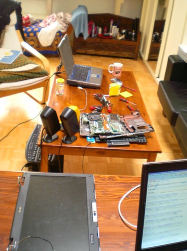
I assembled everything I need: tools, laptop and disassembly guide. Also had a improvised anti-stat wire to keep me grounded.
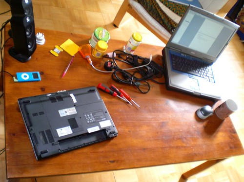
The disassembly guide I found was excellent - I knew exactly which and what order to undo every screw. For anyone else thinking of disassembly, you want these kind of guides if possible.

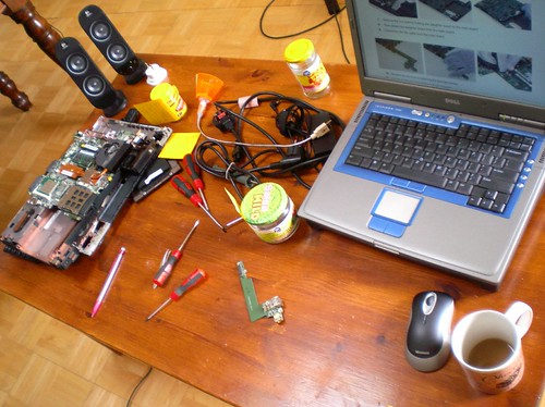
I followed the guide and got the unit apart quite easily.
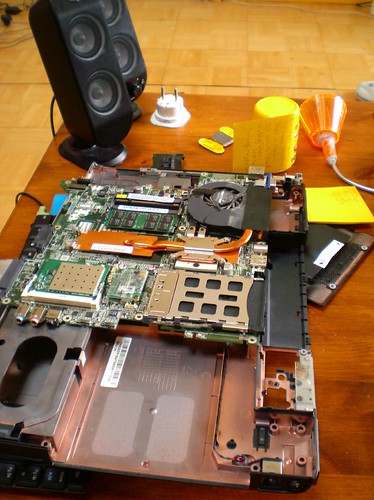
Its really just a motherboard with an upper and lower cover wrapping it. The tricks are in getting the right order of removal, and knowing which wires to unplug
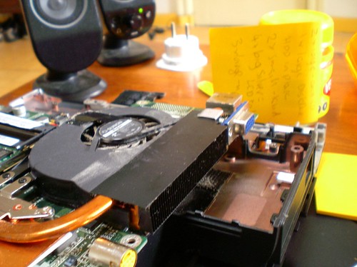
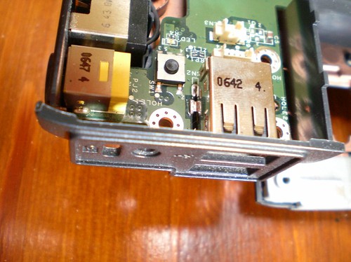
Upon inspection, I found that it was a multilayer board, and I only had a cheap solder iron. This meant I probably couldn't unsolder the socket. What to do? I had to change my low tech solution:
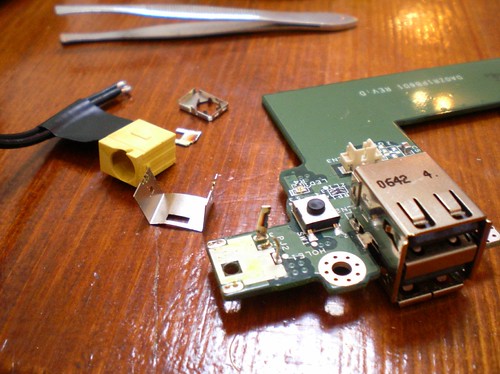
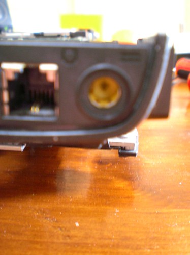
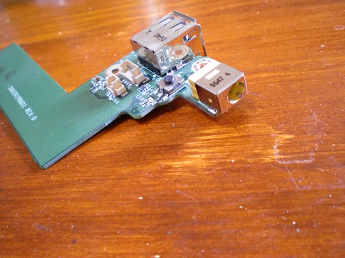
I broke the connector and removed it, while leaving 2 pins to solder to. My technique is non-destructive and hasn't affected the actual board so I can place a new part if/when I find one.
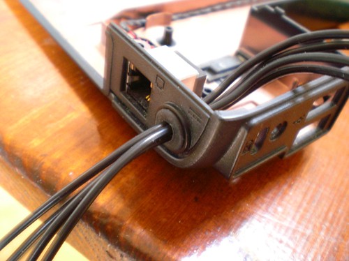
I used a rubber grommet to hold the wires in place. This is very tight, and is the first (and only) defence against yanks of the cable.

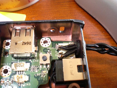
Here is the soldering. Not very pretty but it will work.
I added a standard connector to the other end of the cable, and had to hack the power adapter cable end off too, so its not quite non-destructive...
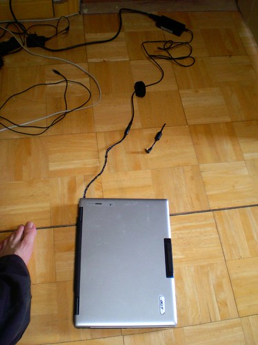
But I can now charge and use it (and get my datas!), which is whats most important. And it only cost $10 Euro to fix.


3 comments:
10 euro? How much for the soldering iron etc. :P
nice mod :)
Haha, you are crazy, but good. Not my cup of thee, good job.
Post a Comment